Experiment 4:
The Magical Multicolor LED1
RED LED Countdown timers are scary
An introduction to for-loops
- main content begins at around the 4 minute mark
- a challenge begins at 14:40
Part 1: I have in my hand a plain, ordinary LED
Introduction
Let’s return to the first circuit we built which controlled a single LED light. Go ahead and create that initial circult.
Discussion
So far we learned how to turn the LED on; how to turn it off; how to blink the LED; and how to blink it in various patterns. In this experiment we are going to learn how to have different levels of brightness. Earlier in the class I said those digital pins can only be on or off and now I am saying the opposite. How can this be?
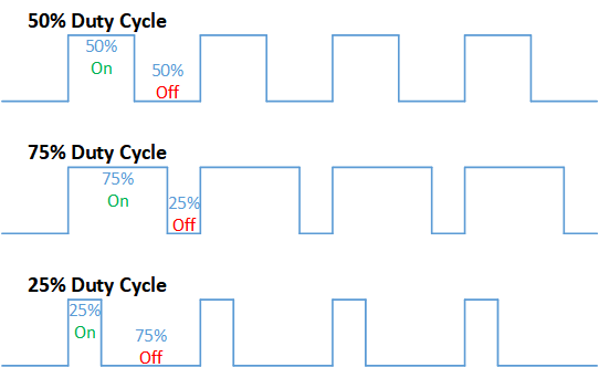
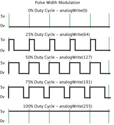
Here is the non-technical explanation. Suppose you are in a room and your little brother quickly turns the lights on and off. Faster and faster. At some point, if your brother is particularly quick, this stops being extremely annoying and instead we stop perceiving the on and off and instead sense a steady dim light. The ons and offs are there but we don’t perceive them. If the offs are a bit longer than the ons the light is dimmer and if the ons are a bit longer than the offs then the light will be brighter. This is called Pulse Width Modulation or PWM.

It uses our digital on and off to make something that looks on the surface as non-digital—a dimmable light. This is pretty cool!
Fortunately, we don’t need to write code that quickly turns the LED on and off. We tell our microprocessor how bright the LED should be, and it takes care of the details.
Here is the scoop.
Instead of using:
digitalWrite(led, HIGH);
we are going to use
analogWrite(led, 255);
The number 255 represents how bright we want the LED. 0 means the LED is off, 255 means the LED is at its brightest, 127 means mid brightness — you get the idea.

The squiggle, the tilde, and pulse width modulation (pwm)
Again, pulse width modulation, means that given a command like
analogWrite(3, 127)
The Arduino Uno will turn pin 3 on and off superfast so the led connected to it will appear to be at half brightness. Only certain pins on the Uno can do pulse width modulation. The ones that can have a squiggle or tilde next to the number.

As you can see, only pins 3, 5, 6, 9. 10, and 11 can do pwm. so
analogWrite(13, 127)
won’t work. Why? Because pin 13 cannot do pwm. For this experiment only connect the leds to the pwm pins.
Binary
You may be wondering why 255? Wouldn’t it better to use some normal number like 100? Here is the reason. And here I am going to get a little geeky.
Decimal numbers or base-10
We are all used to the decimal number system or base 10. In it, each column can have 10 values: 0, 1, 2, 3, 4, 5, 6, 7, 8, 9. In the base 10 system each column represents a power of 10. Starting at the rightmost column and moving leftward we have 10 to the power of zero which equals 1.
                              10^0
                              1
The next column is 10 to the power of 1 which is 10
                    10^1       10^0
                    10         1
The next column is 10 to the power of 2 (10 squared) or 100, and so on.
          10^4   10^3   10^2    10^1    10^0
          10000  1000   100     10      1
Consider a Tesla Model 3 costing $$37,990:
| 10,000 | 1,000 | 100 | 10 | 1 |
|---|---|---|---|---|
| 3 | 7 | 9 | 9 | 0 |
Here we have
- a 3 in the 10,000s column
- a 7 in the 1,000s column
- a 9 in the 100s column
- a 9 in the 10s column
- a 0 in the ones column
So, for example, if we were paying for the Tesla in cash we could use
- 3 ten thousand dollar bills
- 7 thousand dollar bills
- 9 one hundred dollar bills
- 9 tens
- and 0 ones
Binary or base 2
Computers operate on the binary number system, or base 2. In base 2, each column can have one of two values—0 or 1 and each column represents a power of 2. The rightmost column is 2 to the power of 0. The column to the left of that is 2 to the power of 1 and so on:
2^7  2^6   2^5   2^4   2^3   2^2   2^1    2^0
128   64    32    16     8     4     2      1
So if we have a binary number 101, that equals one 4, zero 2s, and 1 one or, to sum that up, 5.
A binary number like 101 is three bits (binary digit) meaning that there are three numbers. A number like 11111111 is an eight bit number. Let’s convert that number to decimal:
| 128 | 64 | 32 | 16 | 8 | 4 | 2 | 1 |
|---|---|---|---|---|---|---|---|
| 1 | 1 | 1 | 1 | 1 | 1 | 1 | 1 |
So that is
- 1 128
- 1 64
- 1 32
- and so on
so
128 + 64 + 32 + 16 + 8 + 4 + 2 + 1 = 255
The smallest number we can represent with 8 bits is 00000000 which in decimal is 0. The largest is 11111111, which is 255.
This is the long explanation of what analogWrite uses the values 0 to 255—because we are using eight bit numbers for it.
A sample program to have a mid-brightness LED light.
int led = 2;

void setup() {
  pinMode(led, OUTPUT);
}

void loop() {
  analogWrite(led, 127);
}
Multi-LED
Use three LEDs for the following remixes. And remember to use variables.
Remix 1 Loopy-Lights™
Can you write code that cycles the LEDs from off, low brightness, medium brightness, high brightness). So constantly off - low - mid - high - off - low - mid - high …
Remix 2 Potentiometer-brightness
Can you write code so that a potentiometer controls the brightness of the LEDs? This code is pretty short. You will have 1 or 2 lines inside the setup procedure and 2 to 3 lines of code inside the loop procedure. When the potentiometer if all the way to the left, the led is off, as you turn the potentiometer gradually to the right the led gets gradually brighter.
Loops
Remember that we have two required parts to a valid Arduino program
void setup()which runs exactly oncevoid loop()which runs over and over and over again.
Suppose we want to write a program that counts down from 100 and prints the number to the serial monitor. That might look like:
 1    int i = 100;
 2
 3    void setup() {
 4      // initialize serial communication at 9600 bits per second:
 5      Serial.begin(9600);
 6    }
 7
 8   void loop() {
 9      Serial.println(i);
10      i = i - 1;
11      delay(1000);
12    }
- So initially
iequals 100. On line 9 we print the value of i, so it prints 100 to the serial monitor. On line 10 we subtract one fromiso nowiequals 99. On line 11 we wait a second and then we loop again. - On line 9 we print the value of
iso we print 99. On line 10 we subtract one so nowiequals 98. and then we loop - On line 9 we print the value of
iwhich is 98. On line line we subtract one so nowiequals 97.
Eventually it prints:
10
9
8
7
6
5
4
3
2
1
0
But it doesn’t stop there and continues:
-1
-2
-3
-4
...
-75421
-75422
...
And on and on our program goes, never stopping until we pull the plug.
Syntactic Sugar
Adding and subtracting from a variable is very common in programming so there are a number of shorthand notations we can use. For example, we can rewrite line 10 (i = i - 1;) as
i -= 1
That is equivalent to
i = i - 1
If we wanted to set i to
i = i - 10
we could write
i -=10
and if we wanted to add 10:
i +=10
We can use another notation if all we want to do is add or subtract 1:
i--  which is equivalent to i = i - 1
i++  which is equivalent to i = i + 1
These different notations don’t add anything to what the computer can do. Anything you can do with the expression
i++
you can do with the orginal
i = i + 1
This type of notation is called syntactic sugar meaning that it is just an alternative way of expressing something, that is easier to read.
We are going to be using these expressions shortly.
for-loop
Now back to our loop.
As we saw above, the void loop() runs forever. In addition, it is quite rare for a computer language to have something equivalent to void loop(). Sometimes we want to loop a specific number of times. For example, maybe we want to print:
10
9
8
7
6
5
4
3
2
1
Blastoff
If we just used
  int i = 10;
  ...
  void loop() {
     Serial.println(i);
     i = i - 1;
     delay(1000);
  }
Our code would print:
10
9
8
7
6
5
4
3
2
1
0
-1
-2
-3
...
-97591
...
So here is a case where we want to stop looping after a certain number of times. Nearly every programming language, including that for the Arduino, has an expression called a for loop which will do exactly that. Its syntax looks like this:
1.  for(int i = 0; i <1 0; i++){
2.    Serial.println(i);
3.  }
4.  Serial.println("Done");
Let’s disect that.
- On line 1,
int i = 0- setsiinitially to 0 - Again on line 1,
i < 10- we read this while i less than 10. So, 0 is less than 10 so we go inside the loop (the lines enclosed in {}) - then we execute what is inside the for block. in this case, we execute line 2.
Serial.println(i). Sinceiis 0 it prints 0. Since that is the only line in the block we go back up to the start of the for-loop, line 1. - In line 1,
i++- now we will change the value ofi.i++indicates that we add 1 toiso nowiis 1. i < 10- now we get back to while i is less than 10. i is now 1 which is less than 10.- then we execute what is inside the for block.
Serial.println(i)which prints 1. - ….
- at some point i = 9
i < 10is still true so we print 9i++we add 1 toiso nowiis 10.i < 10now i is 10 and 10 is not smaller than 10 so we skip the for block and execute the instruction after it which is line 4,Serial.println("Done");and we printDone
The general syntax for the for loop is
for(set a variable to an initial value;
    some test - if true execute block;
    how to change the value of the variable)  {
        the block to execute.
    }
Remix 3: blastoff
Can you write code, using a for loop, that prints to the serial monitor:
10 9 8 7 6 5 4 3 2 1 Ignition Blastoff
Remix 4: a for loopy pulsey light thing
Can you write code so that the lights start dark, gradually increase in brightness and then gradually dim and then repeat?
Here is a puzzler that may help you with one of the above problems. What does the following code do?
int led =3;
int wait = 40;

void setup() {
   pinMode(led, OUTPUT);
}

void loop() {
  for (int i = 0; i < 256;i++){
    analogWrite(led, i);
    delay(wait);
  }
}
If you understand this code, it should provide a clue how to do the loopy pulsey thing. A very rough psuedocode for the loopy pulsey light thing might be
start with the led at 0 and gradually turn it to 255
start with the led at 255 and gradually reduce it to 0
hint The loopy pulsey light should be smooth and you shouldn’t see a hiccup in the brightness. Smooth means that the program should display each level of brightness for the same amount of time. If you have something like
analogWrite(led, 253);
delay(wait);
analogWrite(led, 254);
delay(wait);
analogWrite(led, 255);
delay(wait);
analogWrite(led, 255);
delay(wait);
analogWrite(led, 254);
delay(wait);
...
That program spends twice as long on brightness 255 as it does the others. These lines just illustrate the problem and are not something you will have in your code
Part 2 The Magical Mysterious World of the Multicolor LED
 In this part of the lab we are going to be working with what is called an RGB LED (RGB stands for Red, Green, Blue). There are 4 wires sticking out of this LED. The one we have in our kit is called a Common-Cathode type, which simply means that we connect the long leg to ground. (The other type is the Common-Anode type where we connect the long leg to 5V). Here is a picture that may help:

Let’s pause and look at the common-cathode in that picture
- We are going to connect the - pin to ground on our Arduino Uno
- On one side of the longest leg is a single leg. That leg (R) is connected to the red component of the led. To the other side of the longest leg are two legs. The leg closest to the long leg is the green (G) leg, and the next is the blue (B)
- The R (red) pin we will connected through a resistor to an i/o pin on the Uno (pin 9 for example)
- The G (green) pin will be similarly connected
- The B (blue) pin will also be connected in that way.
- And to make things easier we will define a variable to the pins that each are connected to (
int red = 9for example)
Common Cathode RGB LEDs are easy.
Once we make those connections the common cathode RGB LED works like other LEDs we have worked with.
We can turn on the red component with:
digitalWrite(red, HIGH);
or
analogWrite(red, 255);
and turn off red with
digitalWrite(red, LOW);
or
analogWrite(red, 0);
Fiddling with colors
In this single LED we can fiddle with the brightness of Red, Green, and Blue. For any color we would specify values for each of these. For example, if we wanted solid blue we might have:
analogWrite(red, 0);
analogWrite(green, 0);
analogWrite(blue, 255);
Magenta (aka Fushia) is an equal mix of red and blue so if we wanted a bright magenta we might have:

analogWrite(red, 255);
analogWrite(green, 0);
analogWrite(blue, 255);
If you wanted a dimmer magenta you could do:
analogWrite(red, 127);
analogWrite(green, 0);
analogWrite(blue, 127);
Pink is mostly red with some green and blue:
analogWrite(red, 255);
analogWrite(green, 127);
analogWrite(blue, 127);
Let’s get to work!
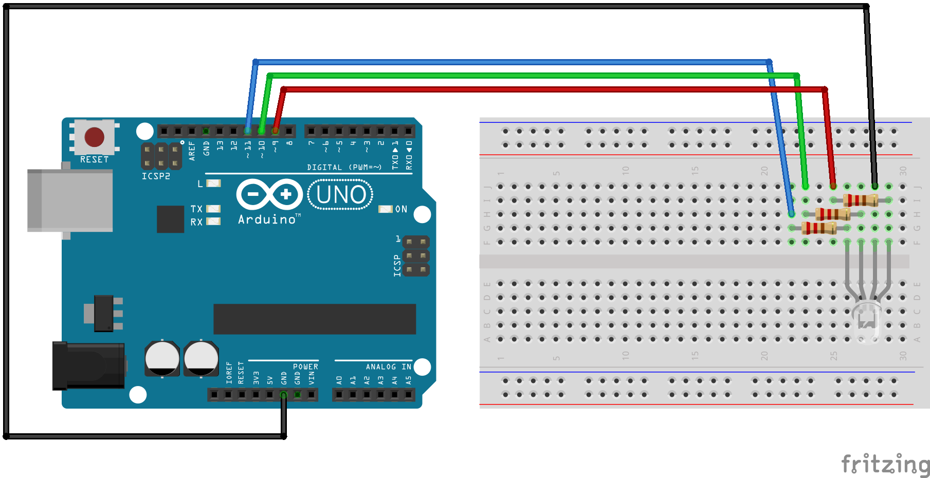
Hardware hookup

The code
And here is code that will display 8 colors just using digitalWrite:
int RED_PIN = 9;
int GREEN_PIN = 10;
int BLUE_PIN = 11;


int DISPLAY_TIME = 100;  // In milliseconds


void setup()
{
  pinMode(RED_PIN, OUTPUT);
  pinMode(GREEN_PIN, OUTPUT);
  pinMode(BLUE_PIN, OUTPUT);
}


void loop()
{

  mainColors();
}


// Here's the mainColors() procedure we've written.

// This procedure displays the eight "main" colors that the RGB LED
// can produce.

void mainColors()
{
  // Off (all LEDs off):

  digitalWrite(RED_PIN, LOW);
  digitalWrite(GREEN_PIN, LOW);
  digitalWrite(BLUE_PIN, LOW);

  delay(5000);

  // Red (turn just the red LED on):

  digitalWrite(RED_PIN, HIGH);
  digitalWrite(GREEN_PIN, LOW);
  digitalWrite(BLUE_PIN, LOW);

  delay(1000);

  // Green (turn just the green LED on):

  digitalWrite(RED_PIN, LOW);
  digitalWrite(GREEN_PIN, HIGH);
  digitalWrite(BLUE_PIN, LOW);

  delay(1000);

  // Blue (turn just the blue LED on):

  digitalWrite(RED_PIN, LOW);
  digitalWrite(GREEN_PIN, LOW);
  digitalWrite(BLUE_PIN, HIGH);

  delay(1000);

  // Yellow (turn red and green on):

  digitalWrite(RED_PIN, HIGH);
  digitalWrite(GREEN_PIN, HIGH);
  digitalWrite(BLUE_PIN, LOW);

  delay(1000);

  // Cyan (turn green and blue on):

  digitalWrite(RED_PIN, LOW);
  digitalWrite(GREEN_PIN, HIGH);
  digitalWrite(BLUE_PIN, HIGH);

  delay(1000);

  // Purple (turn red and blue on):

  digitalWrite(RED_PIN, HIGH);
  digitalWrite(GREEN_PIN, LOW);
  digitalWrite(BLUE_PIN, HIGH);

  delay(1000);

  // White (turn all the LEDs on):

  digitalWrite(RED_PIN, HIGH);
  digitalWrite(GREEN_PIN, HIGH);
  digitalWrite(BLUE_PIN, HIGH);

  delay(1000);
}
What you should see.
After a 5 second delay, you should should see red for a second, followed by green, blue, yellow, cyan, and purple. Then it repeats after a 5 second delay. If you don’t see red after the 5 second delay then:
- if you see either green or blue check your wiring.
- if you see a whitish color you may have a common-anode RGB LED. Check out the appendix below.
Dimmer Red
Here is some code that pulses the red part of the multicolor LED (and introduces the for loop):
	int redLed = 9;
	int greenLed =10;
	int blueLed = 11;
	int display_time = 2; //in milliseconds
	int redColor = 0;
	int blueColor = 0;
	int greenColor = 0;

	void setup() {
	  pinMode(redLed, OUTPUT);
	  pinMode(greenLed, OUTPUT);
	  pinMode(blueLed, OUTPUT);

	}

	void dimmerRed(){
	  // first turn off the green and blue LEDs
	  analogWrite(greenLed, 0);
	  analogWrite(blueLed, 0);


	  // now make red dimmer and dimmer
	  for (int i = 255; i >= 0; i--){
	    analogWrite(redLed, i);
	    delay(display_time);
	  }
	}

	void loop(){
	  dimmerRed();
	}
As you can see, the red light starts at its brightness (value 255) and quickly dims (goes to 0).
Let’s look at the code for the procedure dimmerRed.
- The first things we do is turn off green and blue by using
analogWrite(greenLed, 0)andanalogWrite(blueLed, 0) - Now we start our
forloop. The first time through the loopiis 255, the next time it is 254, then 253 untiliequals -1 and then the loop stops. - Next we have
analogWrite(redLed, i);Initially i is 255 so we set the redLed to brightness 255. The next time through the loop i is 254 so we set the brightness to 254 and so on.
Red and Blue Passing in the Night
Redmix 5: redToBlue-
Can you write a procedure redToBlue so that as the red dims the blue increases in brightness? The format of the procedure is similar to that for dimmerRed. Once you’ve written that procedure change the loop procedure to:
	void loop(){
	  redToBlue();
	}
to test it.
Remix 6: red and blue passing in the night
Ok. Part 1 had you move from red to blue and then there was a sudden jump back to red. Can you modify the code so that the light gradually goes from red to blue and then gradually back again? This may involve writing another procedure.
Remix 7: Roy G Biv - 10-20xp
Roy G Biv - They Might Be Giants
Now we want the multicolor led to go gradually from red to green then green to blue and then blue to red? Think about how you would break this problem down into simple procedures. 10xp for a solution that works, 20xp for code that breaks this task down into simpler subtasks.
Remix 8: Roy G Biv R Vib G Yor
This is a puzzle. What do we want to see?
Appendix: If you have a common-anode RGB LED
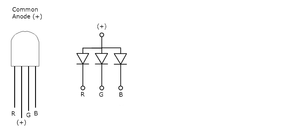
If the above examples are not working correctly you may have a common anode RGB LED. Unfortunately, they look the same. Here is a picture that may help:

Let’s pause and look at that picture
- We are going to connect. the + pin to 3v on our Arduino Uno
- The R (red) pin we will connected through a resistor to an i/o pin on the Uno (pin 5 for example)
- The G (green) pin will be similarly connected
- The B (blue) pin will also be connected in that way.
- And to make things easier we will define a variable to the pins that each are connected to (
int red = 5for example)
Some slight challenges with a common-anode LED.
Having a common-anode RGB LED makes life a tad more difficult interesting. In the above example if we wanted the led off we would write:
analogWrite(led, 0);
and if we wanted full brightness we had
analogWrite(led, 255);
Here’s what I don’t like about common-anode LEDs.
With a common-anode LED things are topsy-turvy. To have a green led off we would have
analogWrite(green, 255);
and if we wanted full brightness we would have
analogWrite(green, 0);
We could also use digitalWrite. In this case
digitalWrite(green, HIGH)
would be off and
digitalWrite(green, LOW);
would be on.