esp8266book
Experiment 1: Blink an LED Light1
Introduction
LEDs (light-emitting diodes) are small, powerful lights that are used in many different applications. To start off our experiments with the ESP8266, we will work on blinking an LED using a digital output. This experiment will also walk you through coding uploading your first sketch with the Arduino IDE.
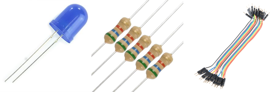
Parts Needed You will need the following parts:
- 1x LED (Choose any color)
- 1x 560Ω Resistor
- 2x Jumper Wires
Hardware Hookup
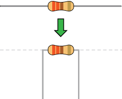
Ready to party? Components like resistors need to have their legs bent into 90° angles in order to correctly fit the breadboard sockets. You can also cut the legs shorter to make them easier to work with on the breadboard.
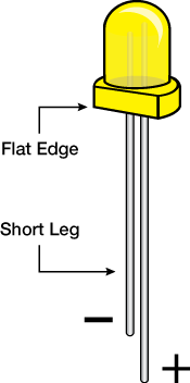
Pay close attention to the LED. The negative side of the LED is the short leg, marked with a flat edge.
Each experiment will have a Fritzing hook-up diagram. Connect the components to the breadboard and Photon RedBoard by following the Fritzing diagram below:

Having a hard time seeing the circuit? Right click on the Fritzing diagram to see a bigger image and select “Open Image in New Tab”
All jumper wires work the same. They are used to connect two points together. All the experiments will show the wires with different colored insulations for clarity, but using different combinations of colors is completely acceptable.
Be sure to the polarity on the LED is correct. The longer lead should be connected to pin 2. You will need to slightly bend the longer leg so that both are the same length when placed int he breadboard.
Installing the software
There are three things you need to install
- The Arduino IDE
- The USB driver (SiLabs CP2104 driver)
- The ESP8266 Board Package
Step 1. Installing the Arduino IDE.
This step is the easiest of the three. The term IDE is a standard computer science one meaning Integrated Development Environment. * It’s sort of a specialized text editor that
- enables you to type in code and save it to a file. Much like Microsoft Word or Mac Pages.
- converts that code into a form that can be read by the Feather Huzzah board.
- transfers the converted code to the Huzzah.
Download and install the Arduino IDE Software from https://www.arduino.cc/en/Main/Software

Now you need to install an Ardiuno IDE add-on that enables us to use our processor boards.
Step 2 Installing the SilLabs Driver
The instructions are here under the headings Don’t forget you will also need to install the SiLabs CP2104 Driver,
Step 3 Installing the ESP8266 Board Package
Instructions for installing this package are in the section Install the ESP8266 Board Package
Write the program to blink the LED light.
Open up the Arduino IDE (the program you just installed in the step above). Then, under the file menu select New and type in the following program
/*
Our First Blink an LED program
*/

// setup runs exactly once
void setup() {
   pinMode(2, OUTPUT);     // Initialize the pin 2 as an output pin
}

// the loop function runs over and over again forever
void loop() {
    digitalWrite(2, HIGH);          // turn on the LED connected to pin 2
    delay(1000);                    // Wait for a second
    digitalWrite(2, LOW);           // turn off the LED
    delay(1000);                     // Wait for one second
}
Next, under the Tools menu under the Board submenu select Adafruit HUZZAH esp8266.**
Then, check your program by clicking on the checkmark icon

The check is optional. It just checks your program for syntax errors. Next you can upload your program to your board by clicking on the arrow icon:

You now should have a blinking LED light.
1: Tutorials are CC BY-SA 4.0. Original page at Sparkfun Inventor’s Kit for Photon. This slight remix by Ron Zacharski